

jwahl
-
Posts
274 -
Joined
-
Last visited
Posts posted by jwahl
-
-
Well my interpretation is that the disk is on that small concrete platform that even shows a 1969 date, and then someone placed a new or reused the old tapered concrete thing over it. It looks sort of 'portable' and can probably be tipped aside, particularly if it had a long pipe in it.
-
You can hope for that, but since the diagram appears to have been created for diminsioning the easements, and shows no ties to the buildings, there is no guarantee that their location is anything but schematic. You have to try anything you can though. It is true that it would not be uncommon for someone to grab an existing plan and reuse it for the current purpose. Can't it be related to the tower as a check?
On the other hand the exterior appears to have been fenced, and maybe there is some evidence of that which can be recovered. Particularly at the SE'ly corner. And that exterior is tied by bearing and distance directly to the station #136, although the basis of bearing is not specifically shown.
- jlw
-
The report of the general survey of Hawaii referenced in SP156 is available on Google Books, and at least one of the beautiful maps is available on the David Rumsey map collection on line. Those mainly deal with cadastral surveys, but the first endeavor was to build up good maps and locations based on sound triangulation system. Much history is contained therein.
I can provide links to those later if anyone is curious.
- jlw
-
I'll add a few more thoughts and then shut up.
First the number of digits that coordinates are reported to does not reflect the accuracy of the position. It didn't in 1916, and it doesn't today. That is just the way they have always done things. We do know that they truncated scaled coordinates though as opposed to adjusted coordinates. But do not believe that because the data sheets report the position to .00001 seconds that the position is actually to a millimeter.
The station WATATICK was reported as third order, and even though it may have been observed from first order stations, the reason it is classified as third order is that for those triangles the observations were only done to third order standards and only third order results can be expected.
There are statements in the preliminary pages to the publication which indicate that the distances given in the table with the positions (which are of course derived from the solutions of the triangles) are reported to 2 more decimals than might be justified by the solution. For WATATICK all the distances are reported to the decimeter, so I think it is safe to say they did not expect the sides to have been solved to better than 1 or 2 meters.
Third order is often specified as 1:5000 or 1:10000 depending on the class. Work of that kind can often exceed those minimums, but it would not be unreasonable on that specification to expect a meter or two of error.
A lot of this is discussed in various forms in the Massachusetts triangulation publication itself.
There could, of course, be blunders in the data capture that show up in the NAD83 adjustment, or some other reason that can only be evaluated if you know specifically what observations were adjusted and the errors found in the network leading to the position.
- jlw
-
To answer your last question, the NAD83 adjustment was not just a change in the ellipsoid. But was based on a slightly different subset of observations. Some observations were undoubtedly dropped out, considerably more data was added and the adjustment was constrained to more certain control. One would hope that the new adjustment would give better results or closer to the truth, but this doesn't always happen given a large sparse network, sometimes the errors get shoved around in funny ways or revealed.
Do we have NAD27 coordinates to compare? I only see them on one of the stations. It would be interesting to see how they related compared to the 1986 and then the most recent adjustments. I suspect the 1986 values look more like the NAD27 differences.
I would have to review history to see how the pre NAD27 North American Datum was actually computed. I would doubt that it was a large scale rigourous least squares. I seem to recall reading that NAD27 didn't even adjust many stations and they were just translated in from the North American Datum. But I do not recall what methods were used for it.
As for the Order of the stations, yes there would be different levels of errors. But the 1922 publication had the same input (namely the triangles measured in 1833 and 1896) as the later adjustment. No GPS observations were used in the 1996 adjustment (I think that first came in 2005 or 2006). In other words no new data accumulated on any of the stations involved after 1896. The only difference (as far as I understand) was the spheroid shape and newer stations outside these triangles whicch may have shifted the triangles around a slight amount.
Another way to state my problem is "why should a datum change" (if that's all that happened) affect the relative distance of 2 stations 7 feet apart".
-
PS to my last post. The early instructions you quote on using nearby stations to find an obscured on is still valid. But you must keep in mind that those stations all have error in them.
So the one station would have gotten you within about a meter in a search for the other, good enough to probably recover the other station.
That was of course written before the day of hand held GPS that can get you nearly that accuracy in the first place. The nearest data point is always the most likely to get you into the right area, but it is not perfect in the same way your GPS handheld is not perfect.
- jlw
-
Maybe I am misreading the information, but it looks to me like both data sheets give coordinates described as being in "NAD 83(1996)" datum and match the ones inversed in the second example.
WATATICK 2 RESET is given as a second order station.
Also it was recovered in 1983 and so it is possible that it has updated GPS coordinates on it that may have been used in later adjustments.
WATATICK is given as a third order station.
To make it a little more clear what I was trying to say before. Adjusted coordinates for these stations would be a result of a least squares adjustment of a number of angles from a variety of other stations in the network. Some of those observations were made a long time ago and they were of varying accuracies and often quit distant. Since it was often the case that only angles were used there can be some error in the adjusted coordinate. Also these stations may even be connected to different stations of varying accuracy.
I would trust the old data sheet as to how far away the station was over a computation made from many miles away which could result in a few feet of error in one or the other station coordinates. When you try to match them up with another station that close, the errors show up. If the stations had been tied together by a distance or direction observation in the recent adjustment then the relationship would have been maintained.
Least squares gives the most probably answer or solution given a specific set of observations, but not an absolute true value. The adjustment probably spit out error ellipses which are not published, but which may be several feet for a 3rd order station determined from stations from 23 - 83 km distant.
I don't know if that puts any perspective on it or not. The locations of the two stations are only partially interdependent and were derived from different data of differing quality.
- jlw
-
Looks like an interesting problem. I have seen something like it before near here. Perhaps Dave Doyle can look up that actual observations that were used in the more recent adjustment. I would tend to believe most the old data. It is very unlikely that the 7 foot difference was observed or used in the adjustment, so each station might be subject to errors coming in from long lines out into the network.
One interesting thing shows up on the old control listed for 2 reset:
MY6361
NAD 83(1996)- 42 41 48.29596(N) 071 53 33.12705(W) AD( ) 2
NAD 83(1992)- 42 41 48.29509(N) 071 53 33.12681(W) AD( ) 2
NAD 83(1992)- 42 41 48.29487(N) 071 53 33.12684(W) AD( ) 2
NAD 83(1986)- 42 41 48.29001(N) 071 53 33.09528(W) AD( ) 2
Note about a 3 foot shift from the first NAD83 value to the second.
- jerry
-
I would be willing to advise on technical details.
Surveying is almost all detective work by nature, finding the records, snooping out what is on the ground, and a mathematical treasure hunt... Gee not that unlike benchmarking.
- jlw
-
I see in your pictures a rather clear outline of cement or something that would indicate to me that a disk was probably there.
I have not reviewed the NGS criteria for 'destroyed', but for horizontal control point purposes, as a surveyor I would probably consider using it subject to later problems which would indicate it isn't right.
The statement that I see
"As a person on Geocaching.com pointed out, even though the disk has clearly been removed, and although their are no local reference marks, a new disk could be set by surveying off distant known points to the (E) and (S)[the view is now obstructed completely between about 270d and 60d, and intermittently by new growth of pine trees in the remaining visible arc]. "
In my opinion no one but NGS should engage in remonumenting, or re-establishing a lost control point that was originally established by them. It is difficult enough to determine an obscured point without a lot of additional work done by others.
The best thing that a benchmarker can do to perpetuate these marks is good documentation, as you have done, of what you found and where it is, so that others can follow, find, and evaluate.
- jlw
Thank you all. I logged MY4714 as DNF.
Mitch, your logic seems correct, but I am 99.44% sure that the drill hole shown is the former position of the disk. But I assume that the "best" I can log here is DNF. BDT, could I actually say "Found" if I were (I am!) dead sure that this is the former station position? And John, I get it that there can be multiple-hole quandries (I have one right now concerning the old "Boulder West of Salem")--I just don't think this is one of them.
 By the way, I didn't know NGS wanted images on anything but claims for Destroyed stations. Would it be helpful to send in these pix to NGS? And do they just get emailed to Deb Brown?
-Paul
-
I see it fine.
You get used to looking for faint marks when looking for marked stones in PLSS surveying. The data sheet describes it pretty well. Is it close to the 15 feet from the gatepost? Hard to tell from your picture.
- jlw
-
If we want to get into instruments that are no longer in production....
or ones that are but are of a higher class...
For those who are more serious about using a compass for surveying there are what we would sometimes refer to as logging compass' or surveying compasses. Another term is "staff compass" which describes the normal use with a jacob staff. K&E was one significant maker and 4-4.5 in. needle models come up frequently on ebay and go for from $100-$200. Then you need to be aware of how to mount it. Some have tripod mounts and most logging type compasses come with an attachment for what is called a jacob staff. Those are hard to find also, but can still be obtained. Their principal purpose was to allow retracement of PLSS lines in the woods and some reasonably accurate line marking.
Warren-Knight produced one of the last high quality compasses of this type, referred to as the "Sipe-Sumner" compass, it is very high quality with a 6-7 inch needle. Sipe was LS #1 in West Virginia and wrote an excellent book which is still readily available on compass surveying. A number of tests he discusses in the book illustrate the high degree of accuracy possible for running lines with such instruments. Some of his tests are with a compass with a 4" needle which is probably a K&E.
A 19th century survey compass is even more refined and typically a 5-6 inch needle and sight vanes 15 in. apart. The slit/wire sites on the Sipe Sumner and K&E compasses are pretty good also without requiring the same size for the instrument.
- jlw
-
I have to admit that I have never verified whether that theory worked out or not. It was just a theory that I have heard to try to explain a 'why'. If the St. Louis difference does not work then perhaps someone decided to use a specific declination from some prior surveys.
I will do more investigation and see if I come up with anything. If the standards and guide meridians all used the same incorrect declination or assumptions then it would never be corrected. It seems like once they got up to southern Missouri someone decided to straighten it out.
- jerry
Jerry:
Thanks for that.
I've heard you speak about the "Arkansas Windage" before, but I don't think I heard a possible explanation for why it may have occurred. It's interesting that this phenomenon is unique to this part of PLSSia.
I've read through the 1815 field notes of Prospect Robbins and Joseph Brown and I don't find any mention of how they set the "variation of the needle" nor do they even mention periodically checking the length of their chains. Some 15 years later in 1830, Deputy Surveyor Nicholas Rightor who did a lot of work in Arkansas establishing townships and sections does mention such things. Apparently in retracing portions of the 5th P.M. he determines that his compass must be set to a variation of 8 degrees to 8 degrees 10 minutes East to coincide with the 5th P.M., and as you say, he perpetuates that direction. One thing that I am unsure of it why doesn't the Arkansas Windage eventually get filtered-out at some Guide Meridian East or West of the 5th P.M.?
In checking historic declinations from the National Geophysical Data Center website, it indicates that the declination at the 5th P.M. initial point was 8d 22' E in 1815 and 8d 36' E in 1830. In St. Louis, the NGDC indicates the declination was 8d 10' in 1820 and 8d 14' in 1830. Based on that it doesn't appear that the declination difference between St. Louis and SE Arkansas would account for the "Arkansas Windage." Of course, the NGDC declination numbers are modeled and are apparently only accurate to about 30 arc minutes.
Do you know of any other information that would give a clue as to what Robbins and Brown actually did other than their terse field notes? Are there other theories that would account for the Arkansas Windage?
Tim Osborn
-
The original GLO surveyors operated under instructions from a particular Surveyor General. In that era the instrument used was the well known survey compass which had a vernier for setting off the declination. Many early instructions provided relatively easy ways to obtain true north at any place from polaris at upper or lower culmination by means of 'pointer stars' in adjacent constellations.
However one theory is that in regards to the 5th PM, it may be that the surveyors set their instruments based on an established meridian or true north line at the surveyor general's office in St. Louis and then proceded down the river and commenced their surveys. The fact that the magnetic declination varies with time and place was known in that time frame, but perhaps not known to everyone.
In any case there is a difference between the proper declination at St. Louis and down in SE Arkansas that one theory has it, they did not correct for and this accounts for what we refer to as the "Arkansas Windage". Apparently other subsequent deputy surveyors used existing lines to set their compasses and perpetuated the basis of bearing which was off.
There is no where else in the PLSS, (except all the oddities in Ohio), where this occurred and most of the PLSS is on the average at least fairly well oriented to true north.
- jlw
It's true that the 5th Principal Meridian does not run due exactly North-South (astronomic, geodetic, true, whatever). Based on what I've observed from USGS 7.5 minute topo maps, the section of the 5th Principal Meridian that runs from the mouth of the Arkansas River to the Initial Point (established by Prospect Robbins and Joseph Brown in 1815) has an azimuth of about 1 degree (1 degree East of "True" North.) However, I don't think this divergence has anything to do with the precession of the Earth. It's my understanding that surveyors in the early 1800's were well aware that polaris appears to rotate around celestial North. That's why they would normally make their star observations at Eastern or Western elongation, when Polaris' East-West motion was minimal and when the azimuth of Polaris could be accurately determined. So in theory, finding "true" North (actually determining magnetic declination) wasn't a problem. I think the problem was in accurately placing the line on the ground using the tools of the day (compass and chain) through heavily forested low-land hardwood swamps.
-
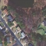
Being that large in diameter it is probably the lid of a monument box. Inside would probably be a monument set to mark the centerlines of the roads for the subdivision. Different jurisdictions have specific monumentation requirements for things like that. If you went to the County Courthouse and try to see or get a copy of the subdivision plat, it will probably show it as a monumented point.
That area has google street level photos, but I can't see the thing very clearly using that.
- jerry wahl
Is this a type of benchmark?
I found this on a residentual street.
Laguna Hills, CA 92653
intersection of Talega Ave /Rio Grande Ave
Near Mandeville Park
N 33, 35.005
W 117, 41.825
I didn't measure it or include anything for a reference , but I think it was about 6 to 9 inch diameter
EDIT
Sorry--I could not upload the photo(Is there a way to upload a photo in a post?)
what this marker said was
"ORANGE COUNTY SURVEYOR"
-
Surveyors have used the Silva Ranger for many years as a favorite sighting compass, but recently the design has changed and they seem to be more cheaply constructed and we have even gotten shipments of defective ones.
The kind that actually has two mirrors in the top lid, the mirrors are poorly fixed with simple double sided tape. The design change provided a sighting slit through the lid, but as a result you have a non planar dual cheap mirror that can fall apart. They may have fixed this defect, but be aware. Originally it was a single piece mirror with a line inscribed on the middle of it. There are a number of places on line that sell the Silva Ranger at $39.95 or so. But then you can't see what you are buying, or many online sites do not picture the product they actually currently have in stock to send you.
Silva is now marketed or owned by an outfit called Tech^4o. http://www.tech4o.com
For a simple compass, the Brunton 9020G Classic Compass is one of the few I have seen that does have a mechanism for setting off the local declination, but there is no sighting mechanism. It is, however, very inexpensive.
Also be aware that there are quadrant compass' and azimuth compass scales. Since your box score is in azimuth, that type may be preferred, but if you do anything with bearings then a quadrant scale is preferred.
- jlw
-
Typically on boundary surveys, or PLSS, an occasional monument is tied in or used by USGS or NGS/CGS for control and it gets published. This is not usually the case. Some state lines have been completely integrated into the control network, probably based on a specific state funded project.
Anyway the point is that specific to your boundary, the little squares you see are most of the mile markers and intermediate markers set in the state line survey and each one should have had a similar monument set. On the Colorado NM boundary both mile posts, and points on ridges and occasionally other points of interest were monumented.
That line was surveyed relatively recently, so they are all nice pipe and brass capped monuments. Many state lines still have stones, or are very old and only fragmentary evidence of the monuments remains.
- jerry
-
Your terminology and procedure is perhaps confusing.
If you have the proper magnetic declination set off on the compass then the bearings read from it will correspond to true bearings. The fact that you are using a compass to determine this does not mean that the bearings are magnetic. If you had set 0 degrees declination on your compass and read it correctly... THEN .. the bearings you obtained would be magnetic.
If your bearings obtained by the compass with the correct declination set off on it, correspond to the data sheet then all is as it should be. But you cannot say that they are magnetic bearings. You can say that they are bearings obtained by a compass with a declination of 15 d W set off. All you need to know and do is state that and you are fine. If it turned out that you had your compass set to 10 degrees west, that would be critical information for anyone trying to interpret your readings.
It is always important when using a compass to know the declination that the compass instrument has set off, and the approximate date that the reading was taken. This would allow anyone following your description to determine what you actually did, and compare it to what the proper settings might be and adjust accordingly.
Compass' can be very confusing in terms of whether the proper declination has been set off -and- whether it is set off in the right direction.
- jl wahl
Answer, "Yes."
For both RM1 at MY4520 and RM1 at MY4530, I took a bearing from the station to the RM, using a handheld Brunton pocket transit adjusted for 15 deg. W declination (so that North bears 345 deg.). In both cases, I believe the readings I obtained came very close (I didn't actually record these readings) to those listed on the datasheets in the box scores for the "Geod. Az" of each RM.
-
One thing to note is that your distance measuring device may be measuring the direct distance between it and your target, but that is what is called 'slope distance' and the data reported on the data sheet will be horizontal distance. The distance must be reduced to horizontal by some accurate means of measuring the angle from the horizontal (or level) line between the points. Some of these gadgets may do that if they contain some sort of vertical sensor. Perhaps it has a level bubble. - jlw
You must have been watching me!
 I got so much sag in my 59 ft. reference distance that I went over to using a contractor-grade hand-held laser distance measuring device that reads out to two decimals in order to report my one decimal place distances, and took at least three measurements for each of the two references. These seemed highly repeatable. This gadget is new to me, but seems to perform well over distances of over 200 ft.
...
But then again, I'd be pretty sure of the reliability of the .1 ft. precision of my hand-held laser. I don't think I'm making unreasonable claims here. [Of course, I don't have any standard to go on in terms oif making these reports...except the opinions of the "real pros"...wait a minute, that is you and Holtie22 after all!
 I'm listening...]
_______________________
-
I generally use a rough approximation mentioned above. 1 second is 'about' 100 feet and 0.01 sec. is 'about' 1 foot. But also remember that the typical recreational grade GPS receiver even with WAAS may only be good to 5-10 feet under ideal conditions. If there is much in the way of structures or tree canopy, this degrades considerably. Averages help a little.
You can do a test yourself by taking a number of positions at a given point at different times and even on different days, and see how much they vary.
I find the most accurate way to navigate to a known point is to use the direction indications from a few points nearby (50 feet of so) and intersect them. Or if you are on the move and in the clear the so called compass screen.
Thank you, GeorgeL and BDT! So a couple of hundredths of a sec. in lat or long is roughly a couple of feet of measurement error on the ground. That's reassuring for some of my past efforts at locating likely detroyed old marks. I will try to repeat your calculations and work an example through FizzyCalc. It's great to have folks like you looking over our shoulders!
-Paul
-
No they are simply as described in the previous posts, nothing to do with a 'human witness' except of course humans set the mark, the RM's the witness post and wrote up the data sheet. I guess the posts are more of the 'bearing silent witness' type.
I was under the impression that the witness post recorded the place of an acutal human witness who observed the setting of the mark.

-
Note about previous post: UTM north and the local town north will be different. So if you do get a listing of a few points in the town system that you can also get UTM on, then you will need to do a transformation which will be a scale, translation and rotation. There are a lot of programs around to do that, or it can be done by hand. Then you can take any number of town coordinates and convert them into UTM.
Did the 1899 map show town coordinates? If so you should be able to use it to compute a conversion.
Coordinates like that are very very common as surveyors set up a simple rectangular grid all the time to do their work and computations. It has primarily only been in the last 15 years with GPS that more surveyors are using State Plane coordinate systems with greater regularity.
So what you need is at least 2 points for which you have coordinates in the local system, and you also have geodetic or UTM coordinates. Then a fairly good transformation can be computed. If the map makes it clear what the orientation of the system is relative to true north, then only one point might be able to be used.
We have a similar system in the D.C. area called WSSC coordinates and is based upon 0,0 being the center of the U.S. Capitol Dome. True north is Grid North at the origin. It has been used for a lot of mapping and infrastructure surveys even out into surrounding counties.
- jlw
I think I need surveyor help on this one...
I thought it would be fun to hunt down all the boundary monuments for my town, and went down to the Town Engineer's Office.
They had a map, but it did not give coords. in Lat/Long or UTM. Instead, it marks each monument with numbers of feet (N) and (W), to 2 decimal places, and the apparent "origin" (0/0 point) appears to be abount .75 mi. (S) and 1.5 mi. (E) of our town.
Apparently these are "surveyor's coordinates" and apparently they can be used to grid our town completely.
I haven't encountered this before. Can someone please tell me where I can go look for an explanation of this type of coordinates? And is there a way I can convert these coordinates into Lat/Long or UTM?
[My town, Winchester, MA, was set off from Woburn in 1852. I stopped by the Woburn City Engineer's Office and received a roughly 16x20" print of a CAD drawing of their city, complete with Lat/Long on each marker and photos of each mark, both from 1899 and from 2002! Wow! They also had a 1899 document, also of folio size, that had the results of the original survey of the city's boundary marks, complete with triangulation diagrams, coords, azimuths, and bearings for each. Wow again!]
Thanks!
-Paul
-
NGS.. Is that the same thing as the oft described 'earthenware cone'? If not I would love to see a picture of one as I may be involved in trying to recover one.
- jlw
-
It sounds like you have one solution. If you do not have a compass that allows you to set off the declination so that IT reads true azimuth, then a good alternative is to convert the true bearings to magnetic.
Let me give an example off the top of my head. If the declination is west 11 degrees, that means that the needle on the compass points to the west of true north and with the compass pointed true north the compass needle would read 349 degrees. Stated another way when your compass is pointing magnetic north or Az of 360 Geodetic Azimuth is 349 degrees. 360m = 349g.
So for a West declination take the true azimuth and add the declination value 349 + 11 = 360 magnetic.
For an East declination you would subtract its value.
Or if you apply a sign convention of W is - and E is plus you would always subtract 349 - (-11) = 360 to go from true to magnetic. Of course the opposite applies going from a magnetic reading to true.
Use any of a number of links available to obtain the current declination for your approximate location and current date.
In MA I would expect a westerly declination of about 15 degrees 10 minutes or 15.2 degrees.
Another possible way to do this is the conversion can be done in many GPS units. Garmins will show you the declination from their built in mag model for wherever you are and can also just be set to show magnetic bearings.
Your RM 1 is listed as azimuth 209-47 (rounded) geodetic azimuth. Following my rule I would add 15d 10' to get 224-57 magnetic, in practice rounded to 225 degrees.
- jlw
PS: It is pretty easy to get which direction to apply the difference confused. Each type of compass has a preferred way of using it, but a compass that can set off the declination is desirable.
I'm not sure I understand what looks like an important concept.
Yesterday I was searching for MY2614 and its three RMs.
In order to locate RM-3 from the station, it seemed that I needed to add the declination back into the "geodetic azimuth" given in the description then take a back bearing (the given bearing minus 180 deg.) to get the compass bearing from the station. Using this technique, I found the RM-3 bolt, but I didn't succeed in finding RMs 1 and 2. Of course, the number of mosquitoes feasting on me while I worked might have had something to do with it...
Help, please.
-Paul
 By the way, I didn't know NGS wanted images on anything but claims for Destroyed stations. Would it be helpful to send in these pix to NGS? And do they just get emailed to Deb Brown?
 I got so much sag in my 59 ft. reference distance that I went over to using a contractor-grade hand-held laser distance measuring device that reads out to two decimals in order to report my one decimal place distances, and took at least three measurements for each of the two references. These seemed highly repeatable. This gadget is new to me, but seems to perform well over distances of over 200 ft.
Need Surveyor Help, Please!
in Benchmarking
Posted · Edited by jwahl
One quick thing to use is a 60p nail or a thing called a barn spike which is similar. Both are like long nails about 6" long and make good temporaty points and can be driven into the ground with a hammer or hatchet if it is not really concrete hard.
There are a dozen ways to construct a search area from RM1. For example you could set a site pole on RM1 and go over the the vicinity of your station and line up a point right on the extension of the line from the RM to the edge of the building. Now you can measure that line the given distance for the RM1 to station. Then take a careful compass bearing from RM1 to that line which will be coincident with the corner of the building (addition).
Now you have your bearing, and can subtract what it is supposed to be to the station per the box score and get an angular difference. Say it is 3.5 degrees. Many simple scientific calculators contain trig functions, so you can now take the sine or tangent of that angle and multiply by the distance and that will give you an offset to go estimating perpendicular to your line. For 3.5 degrees and distance to RM of 98.48 ft, that would give you 6.01 feet offset. That is not perfect because you measured out the full distance on your trial line , but if the angle is small it will not make much difference and the angle or your estimate of perpendicular is not going to be that precise anyway.
If necessary it can be precisely computed the small distance back towards RM1 set off. But I think it would get you within a foot depending mostly on the accuracy of your compass bearing with respect to the plot basis of bearing.
- jlw
PS if you believe that the main part of the building is as reported in the 1953 recovery note you can also measure off 36.7 feet from there and correlate the distances.